Rockchip Sistem Taşıma Süreci, Linux, Android veya OpenHarmony gibi işletim sistemlerinin Rockchip sistem-içinde-çip (SoC) üzerinde sorunsuz bir şekilde çalışması için uyarlanması, derlenmesi ve optimize edilmesini içeren temel mühendislik sürecidir. Bu kapsamlı kılavuz, ortamın başlatılmasından gelişmiş sürücü entegrasyonuna ve performans ayarlamasına kadar tüm kart destek paketi (BSP) geliştirme yaşam döngüsünü adım adım anlatmaktadır. Geliştiriciler, bu kavramları iyice kavrayarak modern silikon platformların donanım potansiyelini en üst düzeye çıkarabilir ve yeni nesil uç cihazlar için uzun vadeli güvenilirliği sağlayabilirler.
Önemli Çıkarımlar
Ekosistem Seçimi: Belirli uç bilgi işlem uygulamaları için Linux, Android, OpenHarmony ve RTOS’u stratejik olarak karşılaştırın.
SDK Mimarisi: Sorunsuz bir yapılandırma için U-Boot, Kernel, Buildroot ve External dizinlerinin hiyerarşik yapısını iyice öğrenin.
Derleme Süreci: Önyükleyiciden rootfs’ye kadar uzanan otomatik ve manuel ürün yazılımı oluşturma süreçlerini yürütün.
Sürücü Taşıma: GPIO’ları, I2C çevre birimlerini ve karmaşık ekran arayüzlerini doğru bir şekilde yapılandırmak için Aygıt Ağacını (DTS) değiştirin.
Performans Ayarlaması: Kurumsal düzeyde donanım uç noktaları için özel olarak tasarlanmış Hızlı Başlatma stratejilerini ve NPU sürücü entegrasyonlarını uygulayın.
Giriş ve Ekosistem Genel Bakışı
Gömülü bir ürünün piyasaya sürülmesi, donanım mimariniz ve uygulama gereksinimlerinizle uyumlu işletim sistemini seçmek gibi kritik bir kararla başlar. Modern Rockchip SoC'ler, çok çekirdekli CPU'lar, yüksek performanslı GPU'lar, özel sinir ağı işleme birimleri (NPU'lar) ve sağlam video işleme motorlarını (VPU) tek bir yonga parçasına sığdıran son derece heterojen tasarımlara sahiptir. Geliştirme döngüsünün erken aşamalarında yanlış işletim sisteminin seçilmesi, ciddi bellek darboğazlarına, gerçek zamanlı teslim tarihlerinin kaçırılmasına veya şişirilmiş yazılım bakım maliyetlerine yol açabilir.
Buna göre Promwad Kenar Yapay Zeka Platformları 2026 Sektör analiz raporuna göre, Rockchip, orta sınıf uç yapay zeka pazarında hesaplama verimi ve birim maliyet arasında en rekabetçi dengeyi sunuyor. Çalışma, RK3588 ve onun ardıl işlemcilerini, rakip mimarilerin yüksek fiyat etiketine sahip olmadan yüksek yapay zeka performansı, esnek multimedya iş akışları ve zengin ekran çıkışları gerektiren işletmeler için tercih edilen platform olarak öne çıkarıyor.
Teknik liderlerin, sistem mimarlarının ve donanım yazılımı mühendislerinin bu seçim sürecinde yolunu bulmasına yardımcı olmak amacıyla, Rockchip ekosisteminde desteklenen başlıca işletim sistemlerini karşılaştırmalı olarak değerlendirdik:
| İşletim Sistemi | Asgari RAM Gereksinimi | Önyükleme Süresi Profili | Birincil Endüstriyel/Ticari Kullanım Senaryosu | Geliştirme ve Bakım Karmaşıklığı |
| Linux (Debian/Ubuntu) | 512 MB – 1 GB | Hızlı (5 – 15 saniye) | Endüstriyel ağ geçitleri, yerel uç yapay zeka sunucuları, başsız otomasyon düğümleri | Orta (Yüksek düzeyde açık kaynak kodlu, geniş topluluk kütüphane desteği) |
| Android (AOSP) | 4 GB – 8 GB | Orta (20 – 40 saniye) | Etkileşimli dijital tabelalar, akıllı perakende POS terminalleri, medya oynatıcılar | Yüksek (Karmaşık HAL katmanı, katı CTS/GMS uyumluluk gereklilikleri) |
| OpenHarmony | 256 MB – 2 GB | Hızlı (5 – 12 saniye) | Dağıtık IoT ağları, akıllı ev aletleri, güvenli akıllı şebeke düğümleri | Yüksek (Hızla gelişen ekosistem, benzersiz HDF sürücü çerçevesi) |
| RTOS (FreeRTOS) | < 16 MB | Anlık (< 1 saniye) | Düşük güç tüketimli algılama düğümleri, gerçek zamanlı motor kontrolörleri, tıbbi aktüatörler | Düşük (Basit görev zamanlayıcı, doğrudan donanım kayıtlarına erişim) |
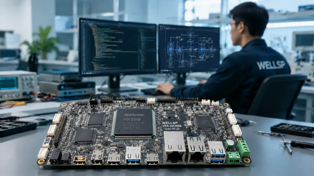
İyi planlanmış bir sistem taşıma iş akışını entegre etmek, yazılımınızın aşağıdakiler gibi gelişmiş platformların performansından tam olarak yararlanmasını sağlar: RK3588 geliştirme kartı. İster yüksek hızlı bir görüntü işleme sistemi tasarlıyor olun, ister son derece dayanıklı bir sistemi devreye alıyor olun endüstriyel ağ geçidi uygulamaları, bu temel ekosistemi anlamak, ürünün başarısına giden yolda atılacak ilk adımdır.
1. Rockchip SDK için Ortam Kurulumu
Tek bir ana bilgisayar kütüphanesinin eksik olması veya uyumsuz bir derleyici sürümü, tüm geliştirme sürecinizi durdurabilir. Rockchip SDK’ları, farklı mimariler arasında derleme yapmak için karmaşık araç zincirlerine dayandığından (genellikle x86_64 ana bilgisayardan Aarch64 hedefine çapraz derleme), standartlaştırılmış ve temiz bir derleme ortamı oluşturmak son derece önemlidir.
Aşağıdakileri çalıştıran özel bir fiziksel makine veya sağlam bir sanal makine kullanmanızı şiddetle tavsiye ederiz: Ubuntu 20.04 LTS veya Ubuntu 22.04 LTS. Daha yeni Linux dağıtımları güncellenmiş paketler sunsa da, bunlar genellikle eski Rockchip BSP katmanlarındaki eski derleme komut dosyalarını çalışmaz hale getiren GCC veya Python ile ilgili kullanımdan kaldırılma sorunlarına yol açmaktadır.
Ana Bilgisayara Bağımlılıkların Başlatılması
Kaynak kodunu indirmeden önce, paket yöneticinizi yapılandırmanız ve zorunlu sistem düzeyindeki bağımlılıkları yüklemeniz gerekir. Ortam kurulumunu tamamlamak için ana bilgisayarınızda aşağıdaki bash betiğini çalıştırın:
#!/bin/bash
# Standart Rockchip BSP Derleme Bağımlılık Yükleyicisi
# Hedef Sistemleri: Ubuntu 20.04 / 22.04 LTS Ana Bilgisayarlar
yankı “Rockchip SDK derleme bağımlılıklarını başlatılıyor…”
sudo apt-get update
sudo apt-get install -y git ssh make gcc libssl-dev liblz4-tool \
g++ patchelf chrpath gawk texinfo chrpath diffstat binfmt-support \
qemu-user-static live-build bison flex fakeroot cmake gcc-multilib g++-multilib \
device-tree-compiler, ncurses-dev, bc, python3-pip, rsynccpio ve libelf-dev paketlerinin sıkıştırılmış dosyalarını aç
yankı “Ana bilgisayar ortamı başarıyla başlatıldı.”
Docker Aracılığıyla Konteyner Tabanlı Derleme
Kurumsal geliştirme ekipleri için, yerel makine yapılandırmalarına güvenmek ortam farklılıklarına yol açar. Bir geliştiricinin makinesinde yapılan bir paket güncellemesi, o geliştiricinin derlemesinin başarılı olmasına neden olurken, başka bir geliştiricinin derlemesinin başarısız olmasına yol açabilir. Bunu ortadan kaldırmak için, standartlaştırılmış bir Docker konteyneri içinde derleme yapmanızı şiddetle tavsiye ederiz. Aşağıda endüstriyel düzeyde bir Dockerfile Rockchip SDK’larının gerektirdiği tam derleme ortamını içeren:
Rockchip SDK Çapraz Derleme için # Dockerfile
ubuntu:20.04'ten
# Paket kurulumu sırasında etkileşimli istemlerden kaçının
ENV DEBIAN_FRONTEND=noninteractive
# Güncelleme ve gerekli bağımlılıkların yüklenmesi
Şunu çalıştırın: apt-get update && apt-get install -y \
git ssh make gcc libssl-dev liblz4-tool expect g++ patchelf \
chrpath gawk texinfo diffstat binfmt-support qemu-user-static \
live-build bison flex fakeroot cmake gcc-multilib g++-multilib \
unzip device-tree-compiler ncurses-dev bc python3-pip rsync \
cpio libelf-dev sudo locales && \
rm -rf /var/lib/apt/lists/*
# Sistem dil ayarını UTF-8 olarak ayarla
locale-gen en_US.UTF-8 komutunu çalıştırın
ENV LANG en_US.UTF-8
ENV LANGUAGE en_US:en
ENV LC_ALL en_US.UTF-8
# Dosya izinleriyle ilgili sorunları önlemek için, ana bilgisayarın UID/GID değerleriyle eşleşecek şekilde root olmayan bir geliştirici kullanıcısı oluşturun
ARG USER_ID=1000
ARG GROUP_ID=1000
RUN groupadd -g ${GROUP_ID} developer && \
useradd -u ${USER_ID} -g developer -m developer && \
echo “developer ALL=(ALL) NOPASSWD:ALL” >> /etc/sudoers
USER geliştiricisi
WORKDIR /home/developer/rk_sdk
SDK kök dizinini bu kapsayıcının içine monte ederek, her derlemenin matematiksel olarak tekrarlanabilir olmasını sağlar ve donanım yazılımı sürüm akışınızı öngörülemeyen ana bilgisayar bağımlılıklarından korursunuz.
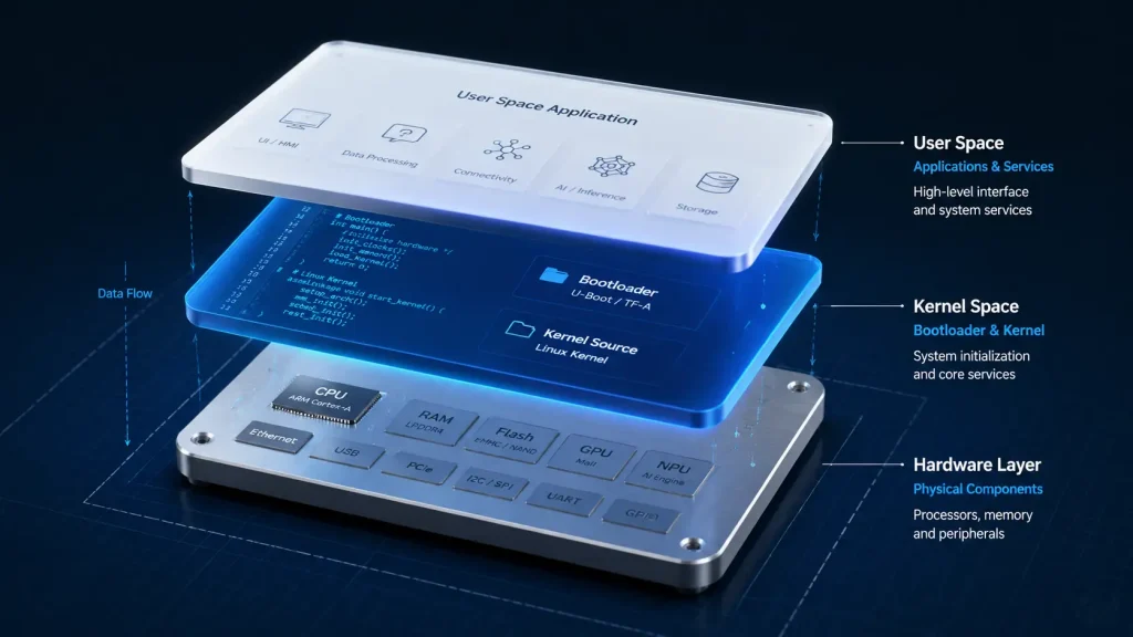
2. Rockchip SDK Mimarisine Derinlemesine Bir Bakış
Tipik bir Rockchip Linux SDK’sı, tam bir derleme işleminden sonra genellikle 50 GB’yi aşan devasa bir dizin ağacıdır. Bu yapıda gezinmek için, her bir üst düzey dizinin üstlendiği farklı rolleri anlamak gerekir.
rk_sdk/
├── app/ # Kullanıcı alanı uygulamaları ve özel demolar
├── buildroot/ # Buildroot sistem oluşturma dosyaları
├── debian/ # Debian kök dosya sistemi oluşturma komut dosyaları ve önceden derlenmiş dosyalar
├── device/
│ └── rockchip/ # Hedef kart yapılandırmaları ve bölüm tabloları
├── external/ # Özel kütüphaneleri (VPU, NPU, MPP HAL'leri)
├── kernel/ # Linux çekirdek kaynak kodu ve aygıt ağaçları
├── prebuilts/ # Çapraz derleyiciler (GCC, Clang) ve ikili araç zincirleri
├── rkbin/ # Özel önyükleme ikili dosyaları (DDR eğitimi, Trust)
├── u-boot/ # Evrensel Önyükleyici kaynak kodu
└── build.sh # Genel orkestrasyon derleme komut dosyası
Kök Dizin Temel İşlevleri
u-boot/: Önyükleyiciyi barındırır. Erken sistem kayıtlarını başlatır verkbin/, depolama denetleyicisini (eMMC/SD/NVMe) yapılandırır ve Linux çekirdeğini sistem belleğine yükler.kernel/: Ana işletim sistemi çekirdeğini içerir. Şu kaynağa göre Linux Çekirdeği Belgeleri, Aygıt Ağacı (DT), kartın fiziksel düzenini sürücü kaynak kodundan tamamen ayıran dinamik bir donanım tanımlama dili olarak işlev görür. Bu klasör, tüm.dtsve.dtsifiziksel kartınızı temsil eden dosyalar.dış/: Rockchip’in kapalı kaynaklı ve açık kaynaklı donanım hızlandırıcılarının bulunduğu yer. Buna Rockchip Medya İşlem Platformu (MPP) donanım hızlandırmalı video kodlama ve kod çözme için; ayrıca donanım tabanlı sinir ağı işlemcisini çalıştırmak için gerekli kullanıcı alanı kütüphaneleri.cihaz/rockchip/: Burada, hedeflediğiniz kartın ayarlarını yaparsınız. İçinde şu tür dosyalar bulacaksınız:BoardConfig*.mkbunlar, bölüm ofsetlerini, çekirdek görüntüsü formatlarını, önyükleme komut satırlarını ve hedef depolama ortamı yapılandırmalarını belirler.
Yapılandırma Mekanizmaları
Rockchip, tarafından yönetilen birleşik bir Makefile yapısı kullanır build.sh kök dizinindeki komut dosyası. Bir derlemeyi başlattığınızda, sistem cihaz/rockchip/ derleyici yolu, hedef mimari (kol veya arm64) ve dosya sistemi türü. Dizinler arasındaki bu bağlantıları anlamak, deneyimli geliştiricilerin temel değerlendirmelerden özel, üretim seviyesinde devre kartı tasarımlarına başarıyla geçiş yapmalarını sağlar.
3. Firmware Derleme Süreci
Derleme sisteminin her bir görüntüyü derlediği tam sırayı anlamak, derleme hatalarını gidermek ve tek tek bölümleri yönetmek açısından hayati önem taşır. Derleme boru hattı, ham kaynak kodunu sistematik bir şekilde flaşlanabilir ikili bölümlere dönüştüren çok aşamalı bir süreçtir.
Belirli bir BoardConfig dosyasını (örn., BoardConfig-rk3588-evb1-lp4-v10.mk) çalıştırarak hedef derleme ortamını başlatır. Bu işlem, derleyiciler, çekirdek yapılandırmaları ve hedef mimariler için değişken eşlemelerini ayarlar.
Önyükleyiciyi derler. Bu adımda, açık kaynaklı U-Boot kodu, rkbin/ (DDR eğitim rutinleri ve ARM Güvenilir Yazılım gibi) çıktı olarak uboot.img ve MiniLoaderAll.bin.
Linux çekirdeğini derler. Bu işlem, standart çekirdek görüntüsünü derler ve insan tarafından okunabilir Aygıt Ağacı Kaynak Dosyaları (.dts) dosyalarını Aygıt Ağacı İkili Dosyaları (.dtb) formatına dönüştürür. Bunlar bir arada şu dosyaya paketlenir: boot.img.
Hedef işletim sisteminin kullanıcı alanını oluşturur. Yapılandırmanıza bağlı olarak, bu işlem Buildroot paketlerini derleyip biçimlendirir ya da önceden yapılandırılmış Debian/Ubuntu kök dosya sistemlerini temiz bir rootfs.img.
Rockchip araçlarını kullanır (afptool ve rkImageMaker) şu metni okumak için parameter.txt dosyayı aç, sektör bölüm ofsetlerini hesapla ve tüm ayrı bölümleri tek bir birleştirilmiş update.img Dosya, toplu üretim flaşlamasına hazır.
Manuel Görüntü İşleme
Otomatikleştirilmiş ./build.sh Bu komut dosyası, sistem genelinde derlemeler için verimlidir; ancak günlük sürücü geliştirme çalışmaları, derleme işlemlerinin daha ayrıntılı bir şekilde gerçekleştirilmesini gerektirir. Özel bir sürücünün hata ayıklamasını aktif olarak yapıyorsanız, SDK’nın tamamını yeniden derlemek gereksiz zaman kaybına neden olur. Bunun yerine, geliştiriciler çekirdeği bağımsız olarak derler ve yalnızca hedef bölümü yazarlar:
# Yalnızca çekirdeği ve aygıt ağaçlarını derle
./build.sh kernel
# Yalnızca önyükleyicinin derlenmesi
./build.sh uboot
# Yalnızca kök dosya sistemini yeniden oluştur
./build.sh rootfs
Bu modüler derleme stratejisi, yineleme döngülerini saatlerden dakikalara indirger ve hedef donanımınızda sürücüde yapılan kademeli değişiklikleri hızla test etmenize olanak tanır.
4. Çekirdek Sürücüsünün Taşınması ve Aygıt Ağacı Değişiklikleri
Özel donanımınıza uyacak şekilde Aygıt Ağacı Kaynağını (DTS) değiştirmek, sistem uyarlama sürecinde en sık yapılan ve en kritik görevdir. Rockchip, standart Linux çekirdek mimarisini kullandığından, sürücülerin fiziksel çevre birimleriyle iletişim kurabilmesi için donanım şemasında yapılan her türlü fiziksel pin yönlendirme değişikliğinin DTS dosyasında doğru bir şekilde eşleştirilmesi gerekir.
Gerçek Hayattan Bir Vaka Çalışması: Mekânsal Kısıtlamaların Aşılması
Yakın zamanda gerçekleştirilen bir endüstriyel otomasyon projesinde, IEEKER, yer kısıtlaması olan elektrik dolaplarının içine standart DIN rayı montajı için tasarlanmış bir uç denetleyici geliştirdi. Fiziksel prototip oluşturma aşamasında, müşterimizin özel olarak tasarlanmış muhafazalarının fiziksel düzeninin, standart kabloların cihazın arkasına takılmasına izin vermediğini fark ettik.
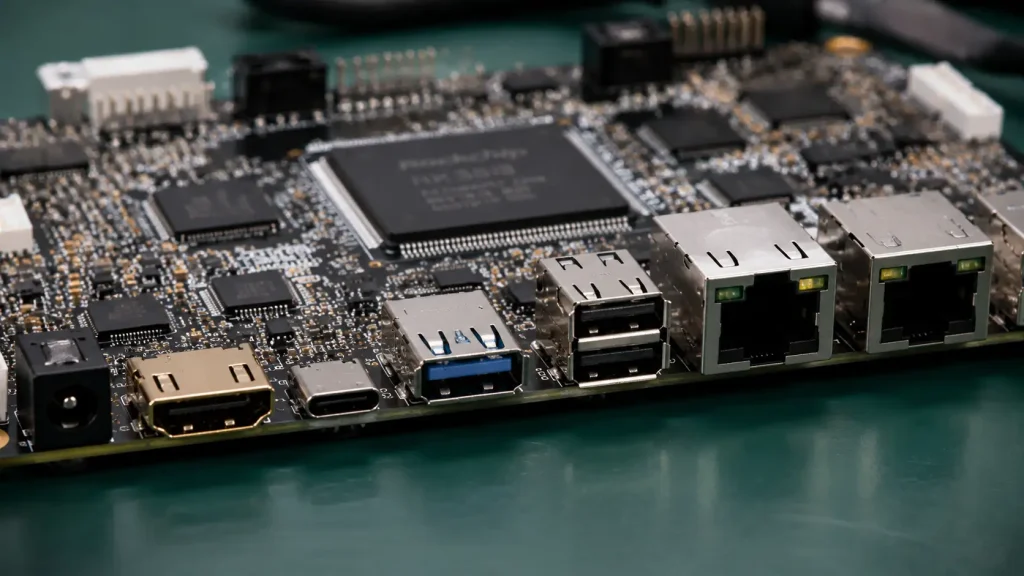
Bu fiziksel kısıtlamayı ortadan kaldırmak için, tüm fiziksel arayüz bağlantı noktalarını arka panel yerine yalnızca yan panele yerleştirmek üzere teknik tasarım özelliklerimizi güncelledik. Bu yapısal değişiklik, özel olarak tasarladığımız anakarttaki bakır izleri tamamen yeniden düzenlememizi gerektirdi; böylece HDMI, USB ana bilgisayar denetleyicileri ve Gigabit Ethernet PHY’leri gibi kritik hatları Rockchip işlemcisindeki tamamen farklı fiziksel pislere kaydırdık.
Bu fiziksel iz yeniden yönlendirme işlemi, DTS yapılandırmamızdaki pin çoklama (IOMUX) bloklarının tamamen elden geçirilmesini gerektirdi. Eğer çekirdeğin pinctrl alt sisteminde, bu yeni bağlantıların eşleştirilmesi projenin ilerlemesini durdurmuş olacaktı. Özel kartımızın DTS dosyasını değiştirerek, yeni yana dönük düzen için elektriksel pull-up/pull-down değerlerini, sürücü güçlerini ve pin çoklama seçeneklerini tek bir öğleden sonra içinde yeniden tahsis ettik ve böylece herhangi bir C sürücü kodunu düzenlemeye gerek kalmadan donanım değişikliğini çözdük.
Standart DTS Çevresel Aygıt Eşlemesi
Aşağıda, kapasitif dokunmatik ekran denetleyicisini üzerinden eşleyen endüstriyel sınıf bir DTS modifikasyonuna ilişkin bir örnek yer almaktadır: i2c1 otobüs:
&i2c1 {
durum = “tamam”;
i2c-scl-yükselme-süresi-ns = ;
i2c-scl-düşüş-süresi-ns = ;
saat-frekansı = ; // I2C saat hızını 400 kHz’e ayarla (Hızlı Mod)
touchscreen@38 {
uyumlu = “edt,edt-ft5x06”;
reg = <0x38>; // Dokunmatik devre kartının I2C donanım adresi
interrupt-parent = <&gpio0>;
interrupts = ; // Kesmeyi GPIO0’ın A5 pinine atama
reset-gpios = <&gpio0 RK_PB4 GPIO_ACTIVE_LOW>; // Sıfırlama işlemini GPIO0’ın B4 pinine atama
touchscreen-size-x = ;
touchscreen-size-y = ;
touchscreen-gpios-delay-ms = ;
durum = “tamam”;
};
};
Bu aygıt ağacı bloğunda:
durum = "tamam"fiziksel olanı mümkün kılari2c1denetleyici.uyumlu = "edt,edt-ft5x06"Linux çekirdeğine, eşleşen öğeyi bağlamasını söyleredt-ft5x06Bu belirli I2C aygıtı için dokunmatik panel sürücüsü.kesmeler =vereset-gpios =donanım kesme ve sıfırlama hatlarını tanımlayın.
Başka bir sürücü (örneğin, bir SPI ana sürücüsü) şunu tanımlamaya çalışırsa RK_PA5 Aynı zamanda, çekirdek, pinctrl kayıt aşamasında bir çakışma hatası verecek ve dokunmatik panel tamamen tepkisiz kalacaktır.
5. Sistem Optimizasyon Stratejileri: RK3588, Android 14 ve Sonrası
Yazılım gereksinimleri değiştikçe, optimizasyon bir zorunluluk haline gelir. Bu durum, özellikle modern işletim sistemlerinin yüksek performanslı yonga setleri üzerinde çalıştırılması söz konusu olduğunda geçerlidir. Örneğin, optimize edilmemiş bir AOSP sisteminin çalıştırılması, yüksek bellek tüketimi, gecikmeli kullanıcı arayüzleri ve yavaş açılış sürelerine yol açabilir.
Hızlı Önyükleme Optimizasyonu
Otomotiv, endüstriyel kontrol ve etkileşimli perakende ortamlarında, uzun soğuk başlatma süreçleri kabul edilemez. Başlatma sürelerini tipik olarak 30 saniyenin üzerindekinden 10 saniyenin altına indirmek, birçok başlatma aşaması boyunca sistematik bir ayarlama gerektirir:
U-Boot Faz Optimizasyonu:
Önyükleme gecikmesini sıfıra ayarlayın (
CONFIG_BOOTDELAY=0) U-Boot yapılandırma dosyanıza ekleyerek, kullanıcı tarafından girilen rastgele geri sayımı atlayabilirsiniz.Önyükleyici programının boş bağlantı noktalarında önyüklenebilir dosyaları aramakla değerli saniyeleri boşa harcamamasını sağlamak için gereksiz önyükleme kaynaklarını (PXE ağ önyüklemesi ve USB depolama aygıtlarının taranması gibi) devre dışı bırakın.
Çekirdek Düzeyinde Eleme:
Çalıştır
menuconfig komutunu çalıştırve kullanılmayan aygıt sürücülerini kaldırın (örneğin, WLAN sürücüleri, eski dosya sistemleri, hata ayıklama çerçeveleri gibiCONFIG_DEBUG_KMEMLEAK).Temel depolama, regülatör ve ekran sürücülerini çekirdeğe statik olarak derleyin (
y) bunları yüklenebilir modüller olarak derlemek yerine (m). Bu sayede, önyüklemenin ilk aşamalarında kullanıcı alanı modül yükleme işlemlerinin getirdiği ek yük önlenir.
Kullanıcı Alanında İşlemlerin Hızlandırılması:
Kritik öneme sahip olmayan sistem hizmetlerini belirleyin ve bunların başlatılmasını geciktirin. Örneğin, ağ yönetimi veya bulut senkronizasyonu arka plan programları yalnızca sonra Ana kullanıcı arayüzü ekranda tamamen yüklendi.
ZRAM Aracılığıyla Bellek Optimizasyonu
Bellek kısıtlı donanım yapılandırmalarında çoklu görev yeteneğini en üst düzeye çıkarmak için sistem mühendisleri ZRAM’ı kullanır. ZRAM, sistem RAM’i içinde sıkıştırılmış, sanal bir blok aygıt oluşturur. Sistem belleği üzerindeki yük arttığında, işletim sistemi etkin olmayan bellek sayfalarını sıkıştırır ve bunları daha yavaş olan flash depolama birimlerine (eMMC/UFS) yazmak yerine ZRAM bölümüne aktarır.
# 2 GB’lık bir ZRAM takas bölümünü başlatmak için örnek çalışma zamanı bash komutları
echo lzo > /sys/block/zram0/comp_algorithm
echo 2147483648 > /sys/block/zram0/disksize # 2 GB sanal blok boyutu ayır
mkswap /dev/zram0
swapon /dev/zram0 -p 32767
8 GB RAM’e sahip bir kartta, 2 GB’lık bir alanı ZRAM takas alanına ayırmak, etkin çoklu görev bellek sınırlarını 10 GB’nin üzerine çıkarabilir; bu sayede arka plandaki işlemlerin hızlı tepki vermesini sağlarken, fiziksel flash bellekteki yazma aşınmasını da azaltır.
Yapay Zeka Hızlandırma ve NPU Entegrasyonu
Modern RK3588 SoC, teorik olarak 6 TOPS’a kadar yapay zeka işleme gücü sunan entegre bir NPU’ya sahiptir. Bununla birlikte, standart Android veya genel Linux sürümleri, yapay zeka işlemlerini genellikle standart kütüphaneler aracılığıyla ana CPU veya GPU üzerinden yönlendirir ve bu özel donanım hızlandırıcısını tamamen atlar.
Bu performanstan yararlanmak için, Rockchip NPU kullanıcı alanı sürücü yığınını entegre etmeniz gerekir (rknn-toolkit2 ve RKNN Çalışma Süresi). Çalışma zamanı ortamı bir köprü görevi görerek, standartlaştırılmış yapay zeka modellerini (ONNX, PyTorch, TensorFlow Lite) özel bir biçime dönüştürür .rknn NPU’nun tensör çekirdekleri için optimize edilmiş format. Sinir ağı çıkarım iş yüklerini özel NPU üzerinden yönlendirerek, geliştiriciler en fazla $10 × $ işlem hızında artış sağlarken, CPU güç tüketimini %'den fazla azaltır.
Yüksek performanslı uygulamalar için bu donanım hızlandırma katmanlarından en iyi şekilde yararlanma konusunu daha ayrıntılı olarak incelemek istiyorsanız, konuyla ilgili hazırladığımız kılavuzu okuyun: RK3588 Üzerinde Android 14’ün Uyarlama Sürecine Derinlemesine Bir Bakış.
6. Sorun Giderme ve Sık Sorulan Sorular
Sistem taşıma, deneme yanılma yoluyla ilerleyen yinelemeli bir süreçtir. Konsol hata mesajlarını nasıl yorumlayacağını ve sistem arızalarını nasıl gidereceğini anlamak, deneyimli BSP mimarlarını acemilerden ayıran unsurdur.
S1: MaskRom modu ile Loader modu arasındaki teknik fark nedir ve bu modlara nasıl zorla girebilirim?
Yükleyici Modu: Bu, yazılım aracılığıyla erişilebilen standart kurtarma modudur. Bu modun çalışması için depolama ortamında işlevsel bir birincil önyükleyicinin bulunması gerekir. Yükleyici modundayken, cihaz USB üzerinden bölüm düzeyinde flash komutlarını kabul edebilir. Bu moda, fiziksel düğmeyi basılı tutarak girersiniz.
İyileşmeCihazı açarken düğmeye basın.MaskRom Modu: Bu, SoC’nin önyükleme ROM’una doğrudan sabit kodlanmış düşük seviyeli bir donanım kurtarma durumudur. Yalnızca depolama aygıtı (eMMC/SPI Flash) tamamen boş veya bozuk olduğunda ya da önyükleyicinin başlatılması başarısız olduğunda çalıştırılır. Güç verilirken eMMC saat (CLK) pini veya SPI Flash yonga seçme (CS) piniyi fiziksel olarak toprağa kısa devre yaparak cihazın MaskRom moduna girmesini zorlayabilirsiniz. Bu işlem, dahili önyükleme ROM'unu bozuk depolama ortamını atlayarak doğrudan bir USB kurtarma kanalı açmaya zorlar.
S2: Derlemem “make” komutunda şu hatayla başarısız oluyor: *** [kernel] Hata 2. Asıl hatayı nasıl bulabilirim?
Paralel derleme (örneğin, make -j16) ölümcül hata meydana geldikten sonra konuyla ilgisiz uyarıları göstermeye devam ederek asıl sorunun kaynağını gizler. Derleme komutunu tek bir iş parçacığıyla yeniden çalıştırın (make -j1 V=1) derleyiciyi, hataya neden olan kod satırında veya eksik bağımlılıkta derlemeyi derhal durdurmaya zorlamak için.
Soru 3: Kart başarıyla yanıp sönüyor ancak U-Boot aşamasında önyükleme döngüsüne takılıyor. Sorun nedir?
Bu durum neredeyse her zaman bir DDR bellek zamanlama sorunu ya da yanlış yapılandırılmış bir bölüm tablosundan kaynaklanır. Sisteminizdeki DDR ikili dosyasının rkbin/ klasör, fiziksel RAM yongalarınızla tam olarak eşleşmelidir (LPDDR4 ve LPDDR4X). Ayrıca, şunun da parameter.txt Dosyanın bölüm ofsetleri, cihazınızın depolama düzeniyle tam olarak uyumludur.
S4: Sistem başarıyla açılıyor, ancak bağlı MIPI-DSI panelinde rastgele yatay çizgiler veya görüntü bozuklukları görülüyor ya da panel tamamen karanlık kalıyor. Bu sorunu nasıl gideririm?
Öncelikle, bir seri hata ayıklama kablosu bağlayın ve kontrol edin dmesg. DSI ana bilgisayarının başlatılamamasıyla ilgili hatalarla karşılaşırsanız, DTS zamanlama parametreleriniz (haktif, vactive, hsync-len, vsync-len) muhtemelen LCD panelinin teknik özellik belgesiyle uyuşmamaktadır. Ana bilgisayar başlatıldığında ekran karanlık kalıyorsa, PWM arka ışık sürücüsünün aygıt ağacında doğru şekilde eşleştirildiğini ve etkinleştirildiğini kontrol edin.
7. Sonraki Adımlar ve Ek Kaynaklar
Güvenilir bir gömülü ürün geliştirmek için sağlam bir temel gereklidir. Geliştirme döngünüzü hızlandırmanıza yardımcı olmak amacıyla, şirket içi referans materyallerimizi tek bir indirilebilir kılavuzda bir araya getirdik.
Temel Geliştirme Araçları
| Kaynak | Belge Odak Noktası | Hedef Kitle |
| IEEKER Komutları Hızlı Başvuru Kılavuzu | En sık kullanılan 50 Rockchip terminal komutu, flash bölümleme komut dosyası ve aygıt ağacı hata ayıklama komutunun yer aldığı özet bir derleme. | Sistem Mühendisleri, Kart Çalıştırma Ekipleri |
| Sistem Mimarisi Kılavuzu | Pim çoklama kuralları, ısı dağılımı teknik özellikleri ve güç durumu yapılandırmalarını ayrıntılı olarak açıklayan kapsamlı yapısal dokümantasyon. | Donanım Tasarımcıları, Yerleşim Mühendisleri |
Günlük geliştirme iş akışlarınızı kolaylaştırmak için, platformlarınızı yazma, hata ayıklama ve test etme işlemlerine yönelik adım adım komutlar içeren, özenle hazırlanmış kaynak kılavuzumuzu indirebilirsiniz.
Özel Teknoloji Merkezlerimizi Keşfedin
Belirli dağıtım senaryolarını daha ayrıntılı olarak incelemek için, hedef odaklı içerik gruplarımızı inceleyin:
Yüksek Performanslı Android Ayarlaması: Kapsamlı teknik analizimizi okuyun: RK3588 Üzerinde Android 14’ün Uyarlama Sürecine Derinlemesine Bir Bakış.
Endüstriyel Ağ Geçidi Kurulumları: Güvenli ortamlar için işletim sisteminizin kapladığı alanı nasıl azaltabileceğinizi öğrenin: RK3568 için Minimalist Bir Debian Sistemi Kurmak.
Dağıtık İşletim Sistemi Mimarileri: Modern donanım sürücü altyapılarını entegre etme konusundaki kılavuzumuzu okuyun: Rockchip SDK ve OpenHarmony: Sürücüler Ohos’a Nasıl Taşınır?.
8. Bir Sonraki Rockchip Projeniz İçin IEEKER ile İşbirliği Yapın
Sistem taşıma ve donanım yazılımı optimizasyonu oldukça fazla kaynak gerektirebilir, ancak bu zorluklarla tek başınıza mücadele etmek zorunda değilsiniz. IEEKER'da mühendislik felsefemiz, geliştirme sürecindeki engelleri ortadan kaldırmaya odaklanmaktadır. Yalnızca yüksek performanslı tek kartlı bilgisayarlar ve geliştirme kartları konusunda uzmanlaşarak, ekibimizin tamamen üretime hazır donanımlar sunmaya ve son derece istikrarlı, kapsamlı bir şekilde belgelenmiş BSP'ler sağlamaya odaklanmasını garanti ediyoruz.
(Lütfen dikkat: Biz tamamen donanım geliştirme kartı tasarımı ve satışı üzerine faaliyet gösteren bir şirketiz; özel PCB montajı veya PCBA üretim hizmetleri sunmuyoruz. Bu sıkı operasyonel odaklanma, mühendislik kaynaklarımızın tamamen temel platformun istikrarına adanmış kalmasını sağlar.)
İster RK3588 üzerinde karmaşık bir çok kameralı görüntüleme sistemi tasarlıyor, ister RK3568 üzerinde dayanıklı bir çift Ethernet iletişim ağ geçidi kuruyor, ister OpenHarmony’nin sınırlarını keşfediyor olun, saha uygulama mühendislerimiz (FAE'ler), şematik inceleme aşamasından özel işletim sistemi derlemesine kadar Ar-Ge süreciniz boyunca size destek olmak için hazırdır.
Önde gelen Ar-Ge ekipleri neden IEEKER’i tercih ediyor:
Üretime Hazır Kart Destek Paketleri: Önceden optimize edilmiş, kurumsal düzeyde Android, Linux ve OpenHarmony dağıtımlarımızla geliştirme süresinden aylarca tasarruf edin.
Geliştiriciden Geliştiriciye Doğrudan Destek: Genel destek masalarını atlayın ve sorunlarınızı doğrudan deneyimli BSP ve sürücü mühendislerimizle çözün.
Yüksek Kaliteli Donanım: Her bir IEEKER geliştirme kartı, zorlu endüstriyel ortamlarda güvenilir bir şekilde çalışacak şekilde tasarlanmış, simüle edilmiş ve dayanıklılık testlerinden geçirilmiştir.
Ürününüzü pazara sunma sürenizi kısaltmanıza yardımcı olalım. Proje gereksinimlerinizi görüşmek, özel görüntü yapıları talep etmek veya donanım değerlendirme birimleri temin etmek için bugün teknik satış ekibimizle iletişime geçin.
Başlamaya hazır mısınız? Teklif Alın bugün.