Портирование систем на платформу Rockchip — это основной инженерный процесс, включающий адаптацию, компиляцию и оптимизацию операционных систем, таких как Linux, Android или OpenHarmony, для их бесперебойной работы на системных чипах (SoC) Rockchip. Это всеобъемлющее руководство проведет вас через весь жизненный цикл разработки пакета поддержки плат (BSP) — от инициализации среды до интеграции расширенных драйверов и настройки производительности. Освоив эти концепции, разработчики смогут раскрыть максимальный аппаратный потенциал современных микросхемных платформ, обеспечив долгосрочную надежность периферийных устройств следующего поколения.
Основные выводы
Выбор экосистемы: Проведите стратегическое сравнение Linux, Android, OpenHarmony и RTOS с точки зрения конкретных сценариев внедрения периферийных вычислений.
Архитектура SDK: Освойте иерархическую структуру каталогов U-Boot, Kernel, Buildroot и External для беспроблемной настройки.
Конвейер компиляции: Выполняйте автоматические и ручные процессы генерации прошивки — от загрузчика до корневой файловой системы.
Портирование драйверов: Измените дерево устройств (DTS) для точной настройки выводов GPIO, периферийных устройств I2C и сложных интерфейсов дисплеев.
Настройка производительности: Внедрите стратегии быстрой загрузки и интеграцию драйверов NPU, специально разработанные для конечных устройств корпоративного уровня.
Введение и обзор экосистемы
Внедрение встраиваемого продукта начинается с принятия важнейшего решения: выбора операционной системы, соответствующей архитектуре вашего оборудования и требованиям приложения. Современные SoC Rockchip отличаются высокогетерогенной архитектурой, объединяющей в одном кристалле многоядерные процессоры (CPU), высокопроизводительные графические процессоры (GPU), специализированные нейронные процессоры (NPU) и мощные движки обработки видео (VPU). Выбор неподходящей операционной системы на ранних этапах цикла разработки может привести к серьезным «узким местам» в памяти, несоблюдению сроков в режиме реального времени или чрезмерно высоким затратам на обслуживание программного обеспечения.
Согласно Платформы Promwad для искусственного интеллекта на периферии, 2026 год Согласно отчету по анализу отрасли, компания Rockchip обеспечивает наиболее конкурентоспособное соотношение вычислительной пропускной способности и удельной стоимости на рынке периферийных решений искусственного интеллекта среднего ценового диапазона. В исследовании отмечается, что процессор RK3588 и последующие модели являются предпочтительной платформой для предприятий, которым требуются высокая производительность в области искусственного интеллекта, гибкие мультимедийные конвейеры и широкие возможности вывода изображения без завышенной цены, характерной для архитектур конкурентов.
Чтобы помочь техническим руководителям, системным архитекторам и инженерам по встроенному ПО сориентироваться в процессе выбора, мы провели сравнительный анализ основных операционных систем, поддерживаемых в экосистеме Rockchip:
| Операционная система | Минимальные требования к оперативной памяти | Профиль времени загрузки | Основной вариант применения в промышленности и коммерческой сфере | Сложность разработки и сопровождения |
| Linux (Debian/Ubuntu) | 512 МБ – 1 ГБ | Быстро (5–15 секунд) | Промышленные шлюзы, локальные серверы искусственного интеллекта на периферии, «бездисплейные» узлы автоматизации | Средний (широкое использование открытого исходного кода, поддержка со стороны огромного сообщества разработчиков библиотек) |
| Android (AOSP) | 4 ГБ – 8 ГБ | Умеренная (20–40 секунд) | Интерактивные цифровые вывески, интеллектуальные POS-терминалы для розничной торговли, медиаплееры | Высокий (сложный уровень HAL, строгие требования к соответствию стандартам CTS/GMS) |
| OpenHarmony | 256 МБ – 2 ГБ | Быстро (5–12 секунд) | Распределенные сети Интернета вещей, «умная» бытовая техника, защищенные узлы «умных» энергосистем | Высокий (быстро развивающаяся экосистема, уникальная среда разработки HDF) |
| RTOS (FreeRTOS) | < 16 МБ | Мгновенный (< 1 секунда) | Сенсорные узлы с низким энергопотреблением, контроллеры приводов, работающие в режиме реального времени, медицинские приводы | Низкий (простой планировщик задач, прямой доступ к регистрам на уровне «bare-metal») |
Внедрение тщательно спланированного рабочего процесса портирования систем гарантирует, что ваше программное обеспечение сможет в полной мере использовать возможности современных платформ, таких как Плата разработки RK3588. Независимо от того, разрабатываете ли вы высокоскоростную систему машинного зрения или внедряете высоконадежную приложения промышленных пограничных шлюзов, и понимание этой базовой экосистемы — первый шаг к успеху продукта.
1. Настройка среды для SDK Rockchip
Отсутствие всего одной библиотеки хост-системы или несовместимая версия компилятора могут привести к остановке всего вашего конвейера разработки. Поскольку SDK от Rockchip используют сложные наборы инструментов для компиляции на разных архитектурах (как правило, это кросс-компиляция с хост-системы x86_64 на целевую архитектуру Aarch64), создание стандартизированной и «чистой» среды сборки имеет первостепенное значение.
Мы настоятельно рекомендуем использовать выделенный физический сервер или надежную виртуальную машину, на которой работает Ubuntu 20.04 LTS или Ubuntu 22.04 LTS. Хотя в более новых дистрибутивах Linux предлагаются обновленные пакеты, они зачастую приводят к появлению проблем, связанных с устареванием GCC или Python, что приводит к сбоям в работе устаревших скриптов компиляции в рамках более старых уровней BSP Rockchip.
Инициализация зависимостей хоста
Перед загрузкой исходного кода необходимо настроить менеджер пакетов и установить обязательные системные зависимости. Для завершения настройки среды выполните следующий скрипт bash на хост-машине:
#!/bin/bash
# — Установщик зависимостей для компиляции стандартизированного BSP Rockchip
Целевые системы #: хост-машины под управлением Ubuntu 20.04 / 22.04 LTS
эхо «Инициализация зависимостей сборки Rockchip SDK…»
sudo apt-get update
sudo apt-get install -y git ssh make gcc libssl-dev liblz4-tool \
expect g++ patchelf chrpath gawk texinfo chrpath diffstat binfmt-support \
qemu-user-static live-build bison flex fakeroot cmake gcc-multilib g++-multilib \
unzip device-tree-compiler ncurses-dev bc python3-pip rsynccpio libelf-dev
эхо «Среда хоста успешно инициализирована».
Компиляция в контейнере с помощью Docker
Для команд разработчиков в крупных компаниях использование локальных конфигураций компьютеров приводит к отклонениям в среде. Обновление пакета на компьютере одного разработчика может привести к успешной сборке у него, в то время как у другого — к сбою. Чтобы исключить эту проблему, мы настоятельно рекомендуем выполнять компиляцию в стандартизированном контейнере Docker. Ниже приведен пример промышленного уровня Dockerfile который содержит именно ту среду компиляции, которая требуется для SDK Rockchip:
Файл Dockerfile # для кросс-компиляции с использованием SDK Rockchip
ИЗ ubuntu:20.04
# Избегать интерактивных запросов во время установки пакета
ENV DEBIAN_FRONTEND=noninteractive
#: Обновление и установка необходимых зависимостей
Выполните команду apt-get update && apt-get install -y \
git ssh make gcc libssl-dev liblz4-tool expect g++ patchelf \
chrpath gawk texinfo diffstat binfmt-support qemu-user-static \
live-build, bison, flex, fakeroot, cmake, gcc-multilib, g++-multilib \
unzip device-tree-compiler ncurses-dev bc python3-pip rsync \
cpio libelf-dev sudo locales && \
rm -rf /var/lib/apt/lists/*
# Установить системные языковые настройки в UTF-8
Запустите команду locale-gen en_US.UTF-8
ЯЗЫК en_US.UTF-8
ЯЗЫК СРЕДЫ en_US:en
ENV LC_ALL en_US.UTF-8
# Создать пользователя-разработчика без прав root с UID/GID, соответствующими UID/GID хоста, чтобы избежать проблем с правами доступа к файлам
ARG USER_ID=1000
ARG GROUP_ID=1000
Выполните команду groupadd -g ${GROUP_ID} developer && \
useradd -u ${USER_ID} -g developer -m developer && \
echo «developer ALL=(ALL) NOPASSWD:ALL» >> /etc/sudoers
Разработчик USER
WORKDIR /home/developer/rk_sdk
Смонтировав корневой каталог SDK внутри этого контейнера, вы обеспечите математическую воспроизводимость каждой сборки, защитив конвейер выпуска прошивки от непредсказуемых зависимостей от хост-системы.
2. Подробное изучение архитектуры SDK Rockchip
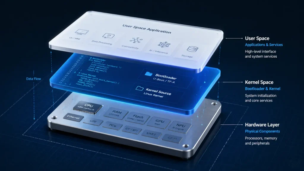
Стандартный набор средств разработки Rockchip Linux SDK представляет собой обширное дерево каталогов, размер которого после полной сборки часто превышает 50 ГБ. Для ориентации в этой структуре необходимо понимать, какие конкретные функции выполняет каждый каталог верхнего уровня.
rk_sdk/
├── app/ # Приложения пользовательского пространства и фирменные демонстрационные версии
├── buildroot/ # Файлы генерации системы Buildroot
├── debian/ Скрипты для генерации корневой файловой системы Debian # и предварительно скомпилированные библиотеки
├── device/
│ └── rockchip/ # Конфигурации целевой платы и таблицы разделов
├── external/ # Собственные библиотеки (HAL для VPU, NPU и MPP)
├── kernel/ Исходный код ядра Linux # и деревья устройств
├── prebuilts/ Кросс-компиляторы # (GCC, Clang) и бинарные наборы инструментов
├── rkbin/ Проприетарные загрузочные бинарные файлы # (обучение DDR, Trust)
├── u-boot/ Исходный код универсального загрузчика #
└── build.sh — скрипт компиляции для глобальной оркестрации #
Основные функции корневого каталога
u-boot/: Содержит загрузчик. Он инициализирует ранние системные регистры, настраивает контроллер DDR с помощью бинарных файлов изrkbin/, настраивает контроллер хранилища (eMMC/SD/NVMe) и загружает ядро Linux в системную память.kernel/: Содержит основное ядро операционной системы. Согласно Документация по ядру Linux, Device Tree (DT) выступает в качестве языка динамического описания аппаратного обеспечения, который полностью отделяет физическую компоновку платы от исходного кода драйвера. Эта папка содержит все.dtsи.dtsiфайлы, представляющие вашу физическую плату.external/: Здесь представлены аппаратные ускорители Rockchip как с закрытым, так и с открытым исходным кодом. Сюда входит платформа Rockchip Media Process Platform (MPP) для аппаратного кодирования и декодирования видео, а также библиотеки пользовательского пространства, необходимые для управления аппаратным процессором нейронных сетей.устройство/rockchip/: Здесь вы настраиваете конкретную целевую плату. Внутри вы найдете такие файлы, какBoardConfig*.mkв которых указываются смещения разделов, форматы образов ядра, строки команд загрузки и конфигурации целевых носителей.
Механизмы конфигурации
Rockchip использует унифицированную структуру Makefile, управление которой осуществляется с помощью build.sh скрипт на корневом уровне. При запуске сборки система считывает конфигурации из устройство/rockchip/ для установки глобальных переменных среды, таких как путь к компилятору, целевая архитектура (рука или arm64), а также тип файловой системы. Именно понимание этих взаимосвязей между каталогами позволяет опытным разработчикам успешно переходить от базовых оценок к созданию индивидуальных проектов плат, готовых к промышленному производству.
3. Конвейер компиляции прошивки
Понимание точной последовательности, в которой система сборки компилирует каждый образ, имеет решающее значение для устранения ошибок компиляции и управления отдельными разделами. Конвейер компиляции представляет собой многоэтапный процесс, в ходе которого исходный код систематически преобразуется в двоичные разделы, готовые к записи во флэш-память.
Инициализирует целевую среду сборки путем загрузки определённого файла BoardConfig (например, BoardConfig-rk3588-evb1-lp4-v10.mk). При этом настраиваются сопоставления переменных для компиляторов, конфигураций ядра и целевых архитектур.
Компилирует загрузчик. На этом этапе происходит объединение кода U-Boot с открытым исходным кодом и проприетарных бинарных файлов в rkbin/ (такие как программы обучения DDR и ARM Trusted Firmware) для вывода uboot.img и MiniLoaderAll.bin.
Сборка ядра Linux. В ходе этого процесса компилируется стандартный образ ядра и осуществляется преобразование исходных файлов дерева устройств (.dts), удобных для чтения человеком, в двоичные файлы дерева устройств (.dtb). Затем они объединяются в boot.img.
Сборка пользовательского пространства целевой операционной системы. В зависимости от вашей конфигурации в ходе этого процесса происходит компиляция и форматирование пакетов Buildroot либо загрузка предварительно настроенных корневых файловых систем Debian/Ubuntu в чистую rootfs.img.
Использует инструменты Rockchip (afptool и rkImageMaker), чтобы прочитать parameter.txt файл, рассчитать смещения секторных разделов и объединить все отдельные разделы в один единый update.img Файл готов к массовому записыванию.
Ручная обработка изображений
Хотя автоматизированная ./build.sh Скрипт эффективен для сборки всей системы, однако разработка драйверов для повседневного использования требует более тонкой настройки компиляции. Если вы активно отлаживаете пользовательский драйвер, пересбор всего SDK занимает лишнее время. Вместо этого разработчики компилируют ядро отдельно и записывают в память только целевой раздел:
# Компилировать только ядро и деревья устройств
./build.sh kernel
# Скомпилировать только загрузчик
./build.sh uboot
# Пересобрать только корневую файловую систему
./build.sh rootfs
Эта модульная стратегия компиляции сокращает время циклов итерации с нескольких часов до нескольких минут, что позволяет быстро тестировать постепенные изменения драйверов на целевом оборудовании.
4. Портирование основного драйвера и изменения в дереве устройств
Внесение изменений в исходный код дерева устройств (DTS) с учетом особенностей вашего оборудования является наиболее частым и важным этапом при портировании системы. Поскольку Rockchip использует стандартную архитектуру ядра Linux, любые изменения в раскладке физических выводов на схеме оборудования должны быть точно отражены в файле DTS, чтобы драйверы могли взаимодействовать с физическими периферийными устройствами.
Практический пример: преодоление пространственных ограничений
В рамках недавнего проекта по промышленной автоматизации компания IEEKER разработала периферийный контроллер, предназначенный для стандартного монтажа на DIN-рейку внутри электрических шкафов с ограниченным пространством. В ходе создания физического прототипа мы обнаружили, что конструктивная компоновка специализированных корпусов нашего клиента не позволяла подключить стандартные кабели к задней панели устройства.
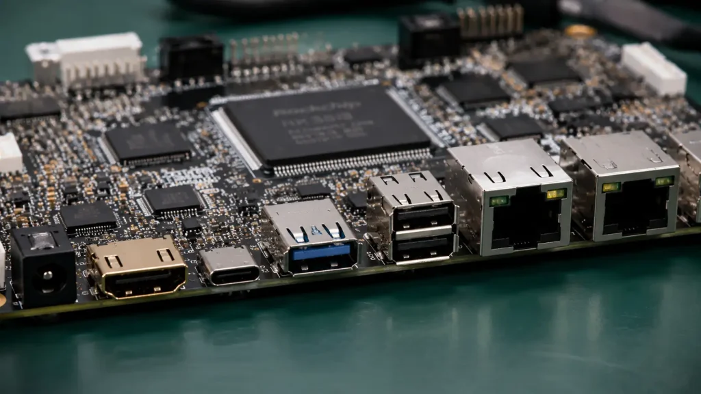
Чтобы устранить это физическое ограничение, мы обновили технические спецификации конструкции, разместив все физические интерфейсные порты исключительно на боковой панели, а не на задней. Это конструктивное изменение потребовало полной перепрокладки медных дорожек на нашей специализированной материнской плате, в результате чего такие важные линии, как HDMI, контроллеры USB Host и физические уровни Gigabit Ethernet, были перенесены на совершенно другие физические выводы процессора Rockchip.
Такая перенастройка трассировки физических сигналов потребовала полной переработки блоков мультиплексирования выводов (IOMUX) в нашей конфигурации DTS. Если бы мы не досконально разобрались в работе ядра, pinctrl подсистеме, налаживание этих новых соединений привело бы к остановке проекта. Изменив файл DTS нашей собственной платы, мы за один день перенастроили значения подтяжки/опускания, уровень мощности сигналов и параметры мультиплексирования выводов для новой компоновки с боковым расположением, решив проблему изменения аппаратной части без редактирования кода драйвера на языке C.
Стандартное сопоставление периферийных устройств DTS
Ниже приведён пример модификации DTS промышленного уровня, обеспечивающей сопоставление контроллера ёмкостного сенсорного экрана с i2c1 автобус:
&i2c1 {
статус = «Хорошо»;
i2c-scl-rising-time-ns = ;
i2c-scl-falling-time-ns = ;
clock-frequency = ; // Установка тактовой частоты I2C на 400 кГц (быстрый режим)
touchscreen@38 {
совместимость = «edt,edt-ft5x06»;
reg = <0x38>; // Аппаратный адрес микросхемы сенсорного экрана по протоколу I2C
interrupt-parent = <&gpio0>;
interrupts = ; // Привязка прерывания к выводу A5 разъема GPIO0
reset-gpios = <&gpio0 RK_PB4 GPIO_ACTIVE_LOW>; // Привязка сигнала сброса к выводу B4 разъема GPIO0
размер-сенсорного-экрана-по-горизонтали = ;
размер-сенсорного-экрана-по-оси-Y = ;
touchscreen-gpios-delay-ms = ;
статус = «Хорошо»;
};
};
В этом блоке дерева устройств:
status = "okay"обеспечивает физическуюi2c1контроллер.compatible = "edt,edt-ft5x06"даёт команду ядру Linux привязать соответствующийedt-ft5x06драйвер сенсорной панели для данного конкретного устройства I2C.прерывания =иreset-gpios =определить линии аппаратных прерываний и сброса.
Если другой драйвер (например, SPI-мастер) попытается объявить RK_PA5 При этом ядро выдаст ошибку конфликта на этапе регистрации pinctrl, и сенсорная панель перестанет реагировать на любые действия.
5. Стратегии оптимизации системы: RK3588, Android 14 и далее
По мере развития требований к программному обеспечению оптимизация становится необходимостью. Это особенно актуально при развертывании современных операционных систем на высокопроизводительных микросхемах. Например, работа неоптимизированной системы AOSP может привести к высокому потреблению памяти, задержкам в работе интерфейсов и длительному времени загрузки.
Оптимизация быстрой загрузки
В автомобильной промышленности, системах промышленного управления и интерактивных розничных средах длительные циклы «холодного» запуска являются недопустимыми. Сокращение времени запуска с типичных 30 с лишним секунд до уровня менее 10 секунд требует системной настройки на всех этапах запуска:
Оптимизация фаз U-Boot:
Установите задержку загрузки равной нулю (
CONFIG_BOOTDELAY=0) в файле настроек U-Boot, чтобы обойти обратный отсчёт, зависящий от ввода пользователя.Отключите ненужные источники загрузки (такие как сетевая загрузка по протоколу PXE и проверка USB-накопителей), чтобы загрузчик не тратил драгоценные секунды на поиск загрузочных файлов на пустых портах.
Отсев на уровне ядра:
Запустить
запустить menuconfigи удалить неиспользуемые драйверы устройств (например, драйверы WLAN, устаревшие файловые системы, среды отладки, такие какCONFIG_DEBUG_KMEMLEAK).Статически скомпилировать в ядро необходимые драйверы устройств хранения, регуляторов и дисплеев (
y) вместо того, чтобы компилировать их в виде загружаемых модулей (м). Это позволяет избежать дополнительных затрат ресурсов, связанных с процедурами загрузки модулей в пользовательском пространстве на ранних этапах загрузки.
Оптимизация пользовательского пространства:
Определите и отложите запуск некритичных системных служб. Например, демоны управления сетью или облачной синхронизации должны запускаться только после Основной пользовательский интерфейс полностью инициализировался на дисплее.
Оптимизация памяти с помощью ZRAM
Для обеспечения максимальной эффективности многозадачности на аппаратных конфигурациях с ограниченным объемом памяти системные инженеры используют ZRAM. ZRAM создает сжатое виртуальное блочное устройство внутри оперативной памяти системы. Когда нагрузка на системную память возрастает, ОС сжимает неактивные страницы памяти и перемещает их в раздел ZRAM, вместо того чтобы записывать их на более медленное флэш-хранилище (eMMC/UFS).
# Пример команд bash, выполняемых во время работы системы, для инициализации раздела подкачки ZRAM объемом 2 ГБ
echo lzo > /sys/block/zram0/comp_algorithm
echo 2147483648 > /sys/block/zram0/disksize # Выделить виртуальный блок размером 2 ГБ
mkswap /dev/zram0
swapon /dev/zram0 -p 32767
На плате с 8 ГБ оперативной памяти выделение 2 ГБ под пространство подкачки ZRAM позволяет расширить эффективный объем памяти для многозадачности до более чем 10 ГБ, обеспечивая оперативную работу фоновых процессов и одновременно снижая износ физической флэш-памяти в результате записи.
Ускорение на базе ИИ и интеграция NPU
Современная система на кристалле RK3588 оснащена встроенным процессором искусственного интеллекта (NPU), обеспечивающим теоретическую вычислительную мощность в области искусственного интеллекта до 6 TOPS. Однако стандартные сборки Android или универсальные сборки Linux часто направляют обработку данных искусственного интеллекта через центральный процессор (CPU) или графический процессор (GPU) с помощью стандартных библиотек, полностью обходя этот специализированный аппаратный ускоритель.
Чтобы в полной мере использовать эти возможности, необходимо интегрировать стек драйверов NPU Rockchip для пользовательского пространства (rknn-toolkit2 и Среда выполнения RKNN). Среда выполнения выступает в качестве моста, преобразуя стандартизированные модели ИИ (ONNX, PyTorch, TensorFlow Lite) в проприетарный .rknn формат, оптимизированный для тензорных ядер NPU. Перенаправляя вычисления по инференсу нейронных сетей через специализированный процессор NPU, разработчики могут достичь производительности до $10\times$ повышение скорости обработки данных при одновременном снижении энергопотребления процессора более чем на 80%.
Чтобы более подробно ознакомиться с возможностями использования этих уровней аппаратного ускорения для высокопроизводительных приложений, ознакомьтесь с нашим специализированным сопутствующим руководством: Подробный анализ процесса портирования Android 14 на RK3588.
6. Устранение неполадок и часто задаваемые вопросы
Портирование системы — это итеративный процесс, основанный на методе проб и ошибок. Умение правильно интерпретировать сообщения об ошибках консоли и устранять сбои в работе системы — вот что отличает опытных архитекторов BSP от новичков.
Вопрос 1: В чём заключается техническое различие между режимами MaskRom и Loader, и как принудительно перейти в них?
Режим загрузчика: Это стандартное состояние восстановления, доступное с помощью программного обеспечения. Для его работы требуется исправный основной загрузчик на носителе данных. В режиме Loader устройство может принимать команды управления флэш-памятью на уровне разделов через USB. Перейти в этот режим можно, удерживая физическую кнопку
Восстановлениекнопку во время включения устройства.Режим MaskRom: Это низкоуровневое состояние восстановления аппаратного обеспечения, жестко запрограммированное непосредственно в загрузочном ПЗУ SoC. Оно запускается только в том случае, если устройство хранения (eMMC/SPI Flash) полностью пустое, повреждено или если загрузчик не может инициализироваться. Вы можете принудительно перевести устройство в режим MaskRom, физически закоротив вывод тактовой частоты eMMC (CLK) или вывод выбора микросхемы SPI Flash (CS) на массу при подаче питания. Это заставляет внутренний загрузочный ПЗУ обойти поврежденный носитель и открыть прямой канал восстановления по USB.
Вопрос 2: При сборке с помощью make возникает сбой: *** [kernel] Ошибка 2. Как определить, в чём именно заключается ошибка?
Параллельная сборка (например, make -j16) скрывает первопричину, продолжая выводить не относящиеся к делу предупреждения после возникновения фатальной ошибки. Запустите команду компиляции заново, указав один поток (make -j1 V=1), чтобы заставить компилятор немедленно остановиться на той самой строке кода или отсутствующей зависимости, которая привела к сбою.
Вопрос 3: Плата успешно мигает, но зацикливается на этапе U-Boot. В чём проблема?
Практически всегда это связано с проблемами с таймингами памяти DDR или с неправильной настройкой таблицы разделов. Убедитесь, что бинарный файл DDR в вашем rkbin/ папка полностью соответствует вашим физическим модулям оперативной памяти (LPDDR4 или LPDDR4X). Кроме того, убедитесь, что parameter.txt Смещения разделов файла точно совпадают со структурой хранилища вашего устройства.
Вопрос 4: Система успешно загружается, но на подключенном дисплее MIPI-DSI появляются случайные горизонтальные линии, артефакты или экран остается полностью темным. Как устранить эту неполадку?
Сначала подключите кабель для отладки по последовательному интерфейсу и проверьте dmesg. Если вы обнаружите ошибки, связанные с невозможностью инициализации хоста DSI, проверьте параметры синхронизации DTS (hactive, vactive, hsync-len, vsync-len) вероятно, не соответствуют техническим характеристикам ЖК-панели. Если хост-устройство инициализируется, но экран остаётся тёмным, убедитесь, что драйвер подсветки с ШИМ-управлением правильно сопоставлен и включён в дереве устройств.
7. Дальнейшие шаги и дополнительные ресурсы
Для создания надежного встраиваемого продукта необходим прочный фундамент. Чтобы помочь вам ускорить цикл разработки, мы собрали наши внутренние справочные материалы в единое руководство, доступное для скачивания.
Основные инструменты разработки
| Ресурс | В центре внимания — документ | Целевая аудитория |
| Справочник по командам IEEKER | Краткий сборник из 50 наиболее часто используемых команд терминала Rockchip, скриптов для разбиения флэш-памяти на разделы и команд отладки дерева устройств. | Системные инженеры, группы по наладке плат |
| Руководство по системной архитектуре | Подробная конструкционная документация, содержащая рекомендации по мультиплексированию выводов, технические характеристики теплоотвода и конфигурации режимов питания. | Разработчики аппаратного обеспечения, инженеры-компоновщики |
Чтобы упростить повседневные рабочие процессы разработки, вы можете скачать наше тщательно подобранное руководство по ресурсам, содержащее пошаговые инструкции по прошивке, отладке и тестированию ваших платформ.
📥 Скачать: Скачайте справочник по командам Rockchip
Познакомьтесь с нашими специализированными технологическими центрами
Чтобы более подробно ознакомиться с конкретными сценариями развертывания, ознакомьтесь с нашими тематическими блоками материалов:
Высокопроизводительная настройка Android: Ознакомьтесь с нашим подробным техническим разбором: Подробный анализ процесса портирования Android 14 на RK3588.
Развертывание решений Industrial Gateway: Узнайте, как сократить объем занимаемой операционной системой памяти для обеспечения безопасности среды: Создание минималистичной системы Debian для RK3568.
Архитектуры распределенных операционных систем: Ознакомьтесь с нашим руководством по интеграции современных базовых компонентов драйверов оборудования: Rockchip SDK против OpenHarmony: как перенести драйверы на Ohos?.
8. Сотрудничайте с IEEKER в рамках вашего следующего проекта с Rockchip
Портирование систем и оптимизация прошивки могут требовать значительных ресурсов, но вам не придется решать эти задачи в одиночку. В компании IEEKER наша инженерная философия направлена на устранение препятствий в процессе разработки. Благодаря строгой специализации на высокопроизводительных одноплатных компьютерах и платах для разработки мы гарантируем, что наша команда полностью сосредоточена на создании готового к производству оборудования в сочетании с чрезвычайно стабильными и тщательно документированными пакетами BSP.
(Обращаем ваше внимание: наша компания занимается исключительно разработкой и продажей аппаратных плат; мы не предоставляем услуги по сборке печатных плат по индивидуальному заказу или производству готовых печатных плат (PCBA). Такая строгое целевое направление деятельности позволяет нам полностью сосредоточить инженерные ресурсы на обеспечении стабильности основной платформы.)
Независимо от того, разрабатываете ли вы сложную многокамерную систему технического зрения на базе RK3588, создаете ли вы надежный коммуникационный шлюз с двумя портами Ethernet на базе RK3568 или исследуете новые возможности OpenHarmony, наши инженеры по практическому применению (FAE) готовы поддержать вас на всех этапах цикла НИОКР — от проверки схем до компиляции ОС под ваши требования.
Почему ведущие научно-исследовательские и опытно-конструкторские группы выбирают IEEKER:
Готовые к производству пакеты поддержки плат: Сэкономьте несколько месяцев времени на разработке благодаря нашим заранее оптимизированным дистрибутивам для Android, Linux и OpenHarmony корпоративного уровня.
Прямая поддержка от разработчика к разработчику: Не обращайтесь в общие службы поддержки — обращайтесь напрямую к нашим ведущим инженерам по BSP и драйверам для устранения неполадок.
Оборудование, отвечающее строгим стандартам качества: Каждая плата разработчика IEEKER проходит этапы проектирования, моделирования и испытаний на нагрузку, чтобы обеспечить надежную работу в суровых промышленных условиях.
Позвольте нам помочь вам сократить сроки вывода продукта на рынок. Свяжитесь с нашей службой технической поддержки уже сегодня, чтобы обсудить требования вашего проекта, заказать сборку образов по индивидуальному заказу или получить тестовые образцы оборудования.
Готовы начать? Получить предложение сегодня.