RK3568/RK3568J
| CPU : | RK3568/RK3568J |
| Architecture : | Cortex-A55 |
| Clock Speed : | 1.8GHz/2.0GHz |
| Memory : | 2/4GB DDR4; 4/8GB LPDDR4X |
| ROM : | 16/32/64/128GB eMMC |
| Operating Systems : | Linux 5.10, Android 11, Ubuntu, Debian 11, OpenHarmony 4.1, AMP |
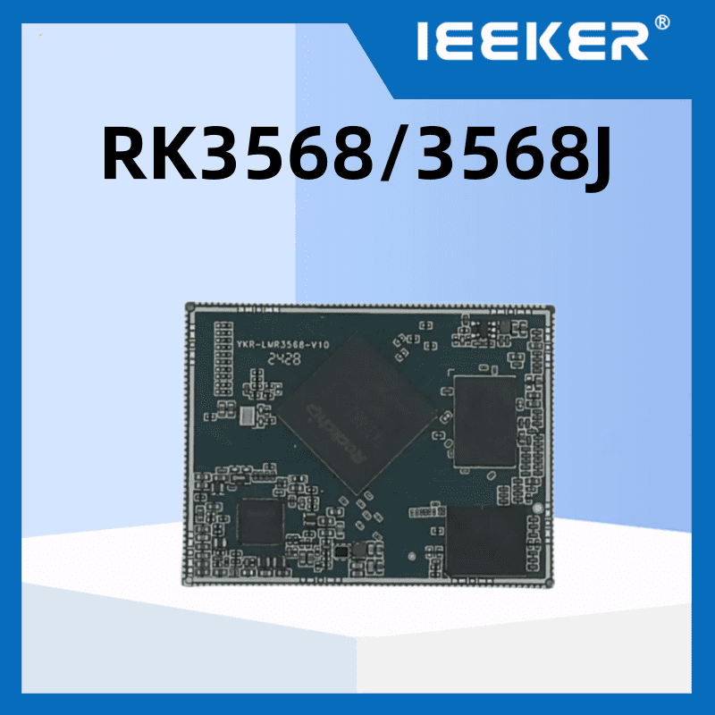
The YKR-CR3568-V1 core board is developed based on the Rockchip RK3568 processor. This processor is a high-performance, low-power, feature-rich domestic application processor specifically designed by Rockchip for the AIoT and industrial markets. It adopts a quad-core 64-bit Cortex-A55 architecture with a clock speed up to 2.0GHz and integrates an NPU. The YKR-CR3568-V1 core board has undergone rigorous environmental temperature testing, pressure testing, and long-term stability operation testing to ensure reliable performance across diverse operational environments.
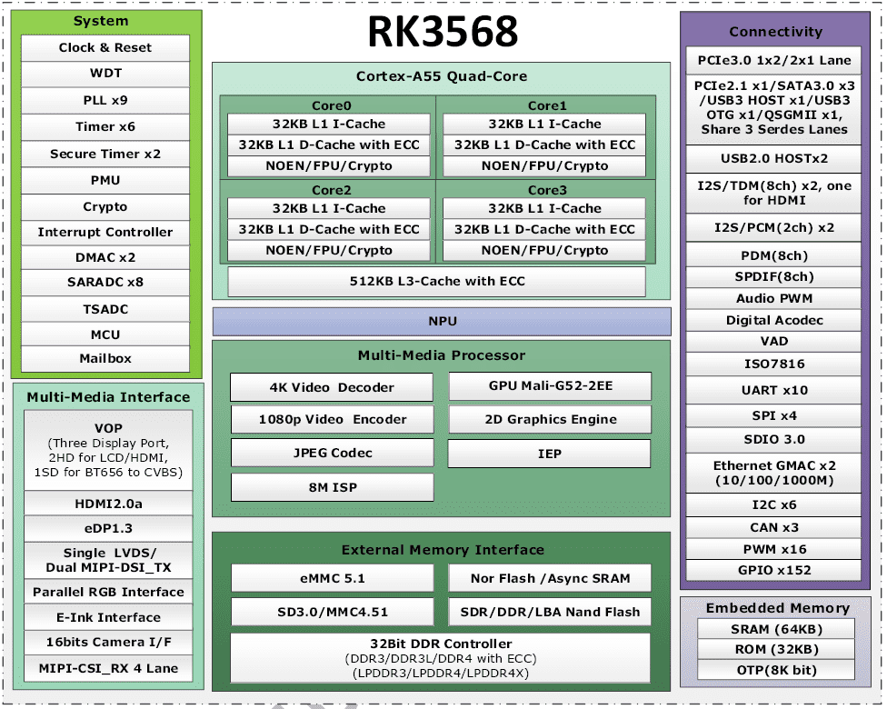
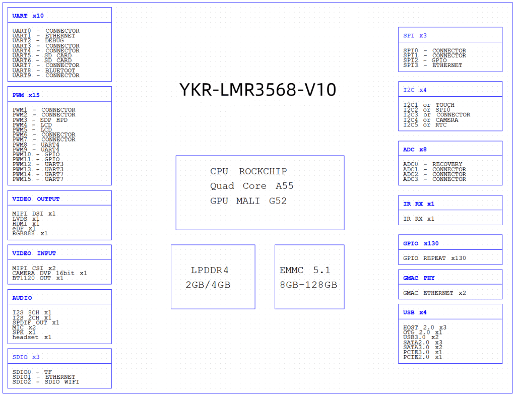
Product Specification:
| YKR-CR3568-V1 Core Board Basic Specifications | |
| Processor | Rockchip RK3568 / RK3568J |
| CPU |
|
| GPU |
|
| NPU |
|
| VPU | Hardware Decoding:
Hardware Encoding:
|
| RAM |
|
| Storage (ROM) | Options: 8GB / 16GB / 32GB / 64GB eMMC |
| Operating System Support |
|
| Power Supply | 5V DC input |
| Interface | Ultra-thin board-to-board connector (4*80pin, 0.5mm pitch) |
| Operating Temperature |
|
| Dimensions | 45mm x 70mm |
| YKR-CR3568-V1 Core Board Functional Specifications | |||
| Function | Quantity | Specifications | |
| Display | 3 | Supports 3 display controllers with simultaneous output of RGB, LVDS, MIPI DSI, HDMI, and eDP interfaces (3 outputs at the same time)
| |
| Camera | 2 | Supports 1 DVP interface and 1 4-lane MIPI-CSI interface | |
| Audio | 4 | 1x 8-channel I2S/TDM, 2x 2-channel I2S, 1x 8-channel PDM | |
| SDIO | 2 | SDIO 3.0, max data throughput up to 104 MB/s | |
| Ethernet | 2 | Dual GMAC interfaces, providing RGMII / RMII interfaces | |
| USB 2.0 | 2 | USB 2.0 Host, independent ports, not shared with USB 3.0 | |
| USB 2.0 | 2 | 1x USB 2.0 Host, 1x USB 2.0 OTG (used as two independent USB 2.0 when USB 3.0 is not in use) | |
| USB 3.0 | 2 | 1x USB 3.0 Host, 1x USB 3.0 OTG | Maximum count; these share 3 SerDes channels, only 3 functional interfaces can be used simultaneously |
| SATA | 3 | SATA 3.0, max rate 6.0 Gb/s, supports eSATA | |
| PCIe 2.1 | 1 | PCIe 2.1 x1, max rate 5.0 Gb/s, Root Complex (RC) mode | |
| PCIe 3.0 | 2 | PCIe 3.0, 1x 2 lanes or 2x 1 lane; each lane max 8.0 Gb/s 1 lane supports only Root Complex (RC) mode 2 lanes support both Root Complex (RC) and End Point (EP) modes | |
| UART | 10 | Max speed 4 Mbps | |
| CAN | 3 | CAN 2.0 B protocol | |
| SPI | 4 | Supports master and slave mode, software configurable | |
| I2C | 5 | Supports 7-bit and 10-bit addressing modes, max speed up to 1 Mbit/s | |
| PWM | 16 | 32-bit timers/counters | |
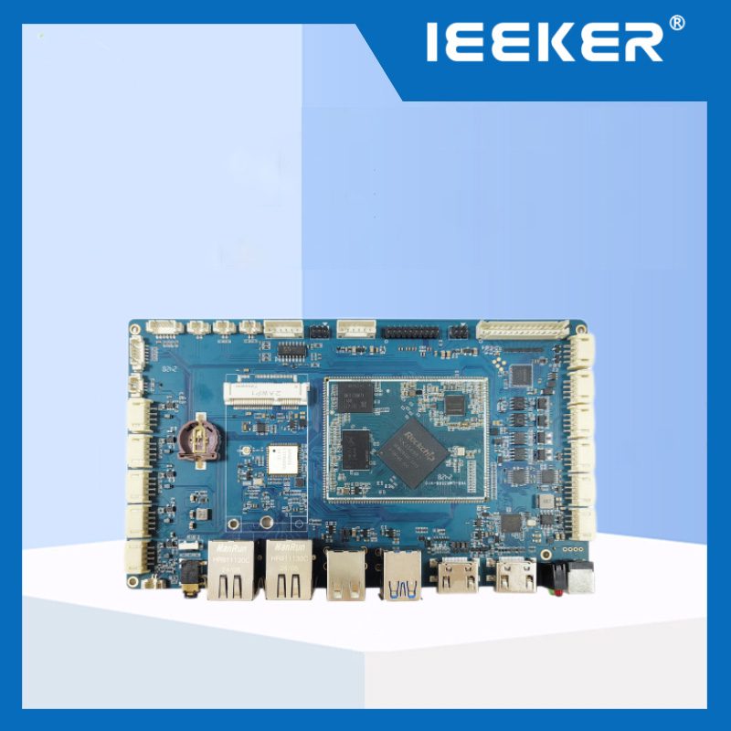
YKR-CR3568-V1 Base Board Interface List | ||
|---|---|---|
| Interface | Description | |
| Display | HDMI 2.0 | Supports up to 1080p@120Hz or 4096×2304@60Hz |
| eDP | Supports eDP 1.3, max resolution up to 2560×1600@60Hz | |
| LVDS | Single-channel output, max resolution up to 1280×800 | |
| LCD | Supports RGB888, max resolution 1280×800; multiplexed with SPI0, SPI2, UART3, UART4, UART5, UART7. Default board configuration uses these interfaces; can be switched to RGB mode via software configuration | |
| MIPI-DSI1 | Single-channel output, max resolution up to 1920×1080@60Hz | |
| Camera | MIPI-CSI interface, compatible with OV13850 camera module | |
| Audio | 1× stereo headphone output; 1× 1.3W Class-D amplifier output; 1× microphone input | |
| TF Card | Supports external storage expansion and OS flashing | |
| Ethernet | 2× 10/100/1000 Mbps adaptive Ethernet ports, RJ45 connectors | |
| 4G / 5G | M.2 Key-B slot with USB 3.0/2.0 interface for 4G/5G module expansion. Supported modules: EM05-CE (4G, EC20-compatible driver), RM500U-CN (5G) | |
| Wi-Fi & Bluetooth | Onboard AW-CM358SM module, dual-band 2.4G/5G Wi-Fi, Bluetooth 5.0. Wi-Fi uses 1× SDIO; Bluetooth uses 1× UART (Note: Bluetooth audio not supported) | |
| USB 2.0 | 2× USB 2.0 Host, Type-A | |
| USB 3.0 | 1× USB 3.0 Host, Type-A | |
| USB 2.0 OTG | Shared with USB 3.0 group; supports device mode for OS flashing and Android ADB debugging | |
| PCIe 2.1 | Standard PCIe x1 slot; pins can be multiplexed as SATA via software configuration | |
| PCIe 3.0 | Standard PCIe x4 slot; configurable via software as 2× PCIe x1 | |
| UART | 3× UARTs, 3.3V TTL level, exposed via 2.54mm pin headers | |
| CAN | 2× CAN 2.0 interfaces with isolation and ESD protection | |
| SPI | 2× SPI, 3.3V TTL level, exposed via 2.54mm pin headers | |
| I2C | 1× I2C, 3.3V TTL level, exposed via 2.54mm pin headers | |
| RTC | Onboard CR2032 battery, maintains time during power-off | |
| Buttons | 8 buttons: Reset, Power, OTG Flash, Maskrom, VOL+, VOL-, HOME, ESC | |
| Debug | Onboard USB-to-UART chip, Type-C interface for easy laptop debugging | |
| Power Supply | DC 12V input | |
Get Quote Now
Get exclusive offers for IEEKER Development Board now. We will provide you with the best solution to help you save more money.
- Guangdong Shenzhen Bao'an Floor 4, Building 12, No.3 Industrial Park, Tangtou South Gang, Tangtou Community, Shiyan Street
- +86 181 2416 7969
- sales@ieeker.com