RK3588
| SOC | Rockchip RK3588 |
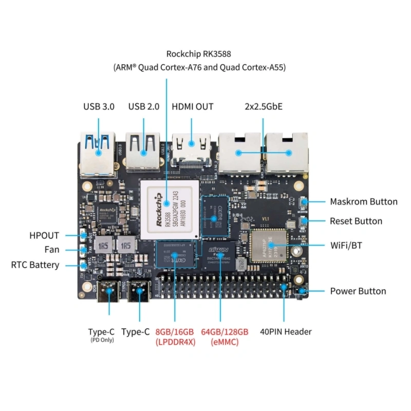
| CPU | RK3588 Quad-core Cortex-A76 @ 2.4GHz + Quad-core Cortex-A55 @ 1.8GHz, 8nm process |
| GPU | ARM Mali-G610 MP4 |
| NPU | Up to 6 TOPS (INT8) computing power, supports INT4/INT8/INT16 hybrid operations |
| Weight | 46.6g |
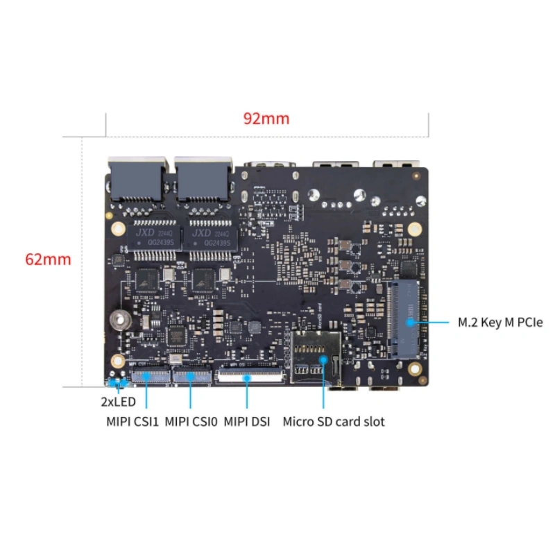
| Dimensions | 92mm × 62mm × 14.6mm |
Introduction
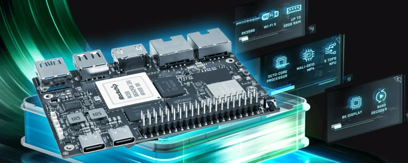
YKR-RK3588 is powered by the Rockchip RK3588, a next-generation flagship octa-core 64-bit processor with a clock speed of up to 2.4GHz. It features an NPU with 6 TOPS of computing power and supports up to 32GB of high-capacity memory.
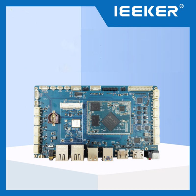
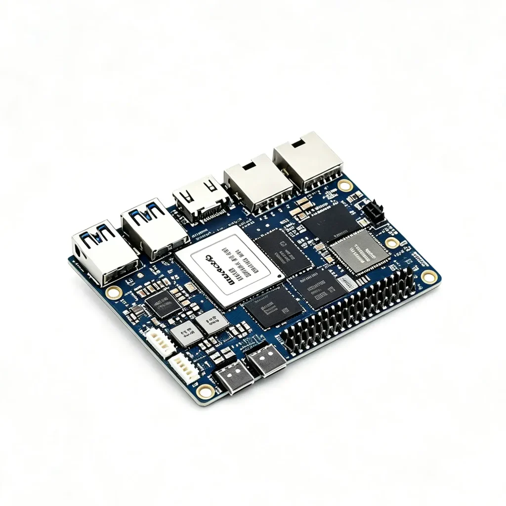
This board supports 8K video encoding and decoding and is equipped with a rich array of interfaces, including dual 2.5G Ethernet ports, WiFi 6 & BT 5.0, and multiple video output options. Supporting a variety of operating systems, it is ideal for applications in ARM PCs, edge computing, cloud servers, AI, cloud computing, VR/AR, blockchain, and intelligent NVR sectors.
RK3588 Hardware Specifications
| Category | Technical Specifications |
| SoC | RockChip RK3588 |
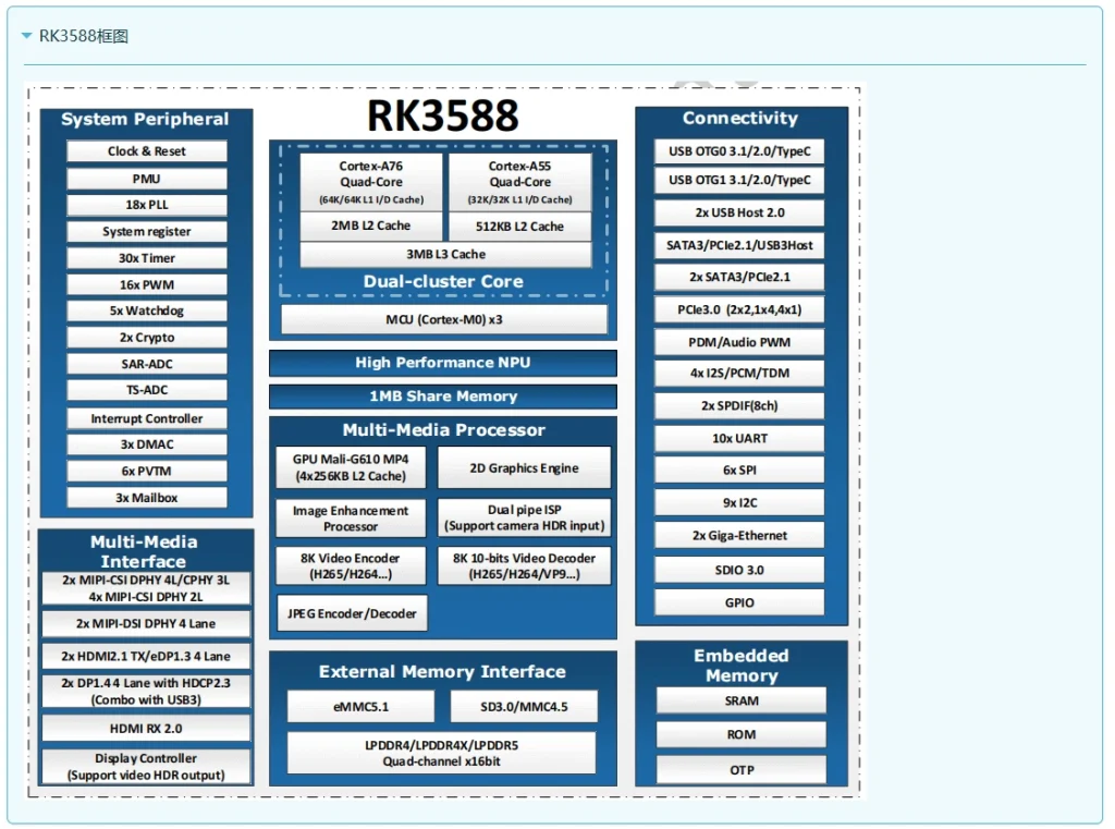
| CPU | RK3588 Quad-core Cortex-A76 @ 2.4GHz + Quad-core Cortex-A55 @ 1.8GHz, 8nm process |
| GPU | ARM Mali-G610 MP4 (4x256KB L2 Cache); Supports OpenGL ES3.2 / OpenCL2.2 / Vulkan1.1 |
| NPU | 6 TOPS @ INT8 (3 NPU cores); Supports INT4 / INT8 / INT16 hybrid operations; Supports deep learning frameworks: TensorFlow, MXNet, PyTorch, Caffe, Tflite, Onnx NN, Android NN, etc. |
| VPU/Codec | Hardware Decoding: 8K@60fps H.265/VP9/AVS2, 8K@30fps H.264 AVC/MVC, 4K@60fps AV1, 1080P@60fps MPEG-2/-1/VC-1/VP8; Hardware Encoding: 8K@30fps H.265 / H.264 |
| ISP | Integrated 48MP ISP with HDR & 3DNR |
| RAM | 8GB / 16GB / 32GB (Maximum 32GB supported); 64bit LPDDR4 / LPDDR4x, default 8GB LPDDR4x |
| Flash | 16GB / 32GB / 64GB / 128GB eMMC, default 64GB eMMC; Supports MicroSD card expansion |
| PCIe | 1x M.2 Key M interface (PCIe 3.0 4-lanes); Expandable SSD: Type 2280 / 2260 / 2242 / 2230, default 2280 |
| Network | • 2x 2.5G Ethernet ports • Onboard IEEE 802.11a/b/g/n/ac/ax WiFi 6 and BT 5.0 (AP6275P) |
| Video Output | • 1x HDMI OUT 2.1, supports 8K@60fps • 1x MIPI DSI, resolution up to 4K@60fps • 1x DP 1.4, resolution up to 8K@30fps |
| Video Input | • 2x 4-Lanes MIPI CSI, up to 2.5Gbps per lane |
| Audio | • 1x HDMI audio output • 1x HP-OUT audio output • 1x USB Type-C 3.0 (DP 1.4) audio output |
| USB Interface | • 1x USB 3.0 (supports USB 3.1 Gen1), up to 5Gbps data rate • 1x USB Type-C 3.0 (DP 1.4 / OTG) • 1x USB 2.0, supports High-Speed (480Mbps), Full-Speed (12Mbps), and Low-Speed (1.5Mbps) modes |
| 40-PIN | • Fully compatible with Raspberry Pi 40-pin, allows for rich peripheral expansion • Supports UART / SPI / I2C / I2S / PWM / ADC / 5V Power / 3.3V Power |
| Others | • 1x 5V Fan interface • 1x Battery input connector for low-power RTC chip LK8563S power supply • 2x LEDs: Green light flashes during normal operation, Red light is user-controlled |
| Power | • Wide range input voltage 5V-23V: Supports USB Type-C PD 2.0, 9V/2A, 12V/2A, 15V/2A, 20V/2A |
| Buttons | • 1x PWRON button, supports sleep/wake-up • 1x Reset button, supports system reboot • 1x Maskrom button, supports entering Maskrom flashing mode |
| OS Support | • Official Rockchip Support: Android 12.0, Debian 11, Buildroot • Third-party Support: Armbian, Ubuntu 20.04, Ubuntu 22.04, Kylin OS |
| Dimensions | 92 mm x 62 mm x 14.6 mm |
| Weight | 46.6g |
| Operating Temp | 0°C ~ 80°C |

| Pin | Signal Name | Description |
| 1, 4, 7, 10, 13, 16 | PGND/SGND | Ground Layer – PGND: Power Ground (High current path) – SGND: Signal Ground (Low noise reference) |
| 2 | MIPI_CSI0_RX_D3N | MIPI CSI-2 Receive Channel 3 – Differential negative input (100Ω ±10% termination matching) |
| 3 | MIPI_CSI0_RX_D3P | MIPI CSI-2 Receive Channel 3 – Differential positive input |
| 5 | MIPI_CSI0_RX_D2N | MIPI CSI-2 Receive Channel 2 – Differential negative input |
| 6 | MIPI_CSI0_RX_D2P | MIPI CSI-2 Receive Channel 2 – Differential positive input |
| 8 | MIPI_CSI0_RX_CLK1N | Secondary Clock Channel – Differential negative (Up to 1.5GHz) |
| 9 | MIPI_CSI0_RX_CLK1P | Secondary Clock Channel – Differential positive |
| 11 | MIPI_CSI0_RX_D1N | MIPI CSI-2 Receive Channel 1 – Differential negative input |
| 12 | MIPI_CSI0_RX_D1P | MIPI CSI-2 Receive Channel 1 – Differential positive input |
| 14 | MIPI_CSI0_RX_D0N | MIPI CSI-2 Receive Channel 0 – Differential negative input |
| 15 | MIPI_CSI0_RX_D0P | MIPI CSI-2 Receive Channel 0 – Differential positive input |
| 17 | MIPI_CSI0_RX_CLK0N | Primary Clock Channel – Differential negative |
| 18 | MIPI_CSI0_RX_CLK0P | Primary Clock Channel – Differential positive |
| 19 | MIPI_VSYNC | Vertical Sync Signal – 1.8V LVCMOS level |
| 20 | MIPI_CAM3_CLKOUT | Sensor Clock Input – 1.8V ±5% |
| 21 | MIPI_HSYNC | Horizontal Sync Signal – 1.8V LVCMOS level |
| 22 | MIPI_CAM1_CLKOUT | Sensor Clock Input – 1.8V ±5% |
| 23 | MIPI_CSI0_PDN0_H(GPIO1_B0) | Power Down Control – 1.8V GPIO, Active High |
| 24 | I2C3_SCL_M0_MIPI | I2C Clock Line – 1.8V Open-drain output |
| 25 | I2C3_SDA_M0_MIPI | I2C Data Line – 1.8V Open-drain output |
| 26 | MIPI_CSI0_PDN1_H(GPIO1_A7) | Secondary Power Down Control – 1.8V GPIO, Active High |
| 27 | CM_RST_L(GPIO4_A0) | Camera Module Reset – 3.3V LVCMOS level, Active Low |
| 28, 29 | VCC_RX | 3.3V Power Rail – Output, Tolerance ±5% |
| 30, 31 | VCC_5V0 | 5.0V Power Rail – Output, Tolerance ±5% |
Get Quote Now
Get exclusive offers for IEEKER Development Board now. We will provide you with the best solution to help you save more money.
- Guangdong Shenzhen Bao'an Floor 4, Building 12, No.3 Industrial Park, Tangtou South Gang, Tangtou Community, Shiyan Street
- +86 181 2416 7969
- sales@ieeker.com